Heat Pump Wiring Diagram Schematic
Heat pump wiring diagram schematic is a critical component of any heat pump system. Without a proper wiring diagram, it can be challenging to install or repair a heat pump.
Common Issues with Heat Pump Wiring Diagram Schematic
Heat pump wiring diagram schematic can be intimidating for those new to HVAC systems. However, it's essential to understand the wiring diagram to install, maintain, or repair a heat pump system. Some of the most common issues related to heat pump wiring diagram schematic include incorrectly wired thermostats, blown fuses, and faulty motors.
What is the Target of Heat Pump Wiring Diagram Schematic?
The target of heat pump wiring diagram schematic is individuals who want to learn about the wiring diagram of heat pump systems, including installation, maintenance, and repair. This guide will provide a comprehensive overview of heat pump wiring diagram schematic and related keywords
Main Points Related to Heat Pump Wiring Diagram Schematic
Heat pump wiring diagram schematic is essential in the installation, maintenance, and repair of heat pump systems. Wiring diagrams can be intimidating for beginners, but proper knowledge of the wiring diagram is necessary to avoid common issues such as wiring the thermostat incorrectly, a blown fuse, or a faulty motor.
Understanding Heat Pump Wiring Diagram Schematic
Most heat pump systems operate on a similar wiring system. The wiring diagram's primary components are the compressor, reversing valve, thermostat, fan, capacitor, and the outdoor and indoor units. It's essential to understand the wiring diagram's symbols and follow the wire color codes to avoid any confusion or mistakes.
One critical aspect of the wiring diagram is the thermostat's wiring, which controls the heat pump system's operation. The thermostat wire colors include red, green, yellow, and blue. The red wire is the power supply, green is for the fan, yellow is for the compressor, and blue is the common wire.
Common Mistakes in Heat Pump Wiring Diagram Schematic
As mentioned earlier, incorrectly wiring the thermostat is one of the most common mistakes made during heat pump installation or repair. Another issue is using the wrong wire size or gauge, which can lead to overheating and fires. It's also essential to use the correct voltage and amperage to avoid costly damages.
Electrical Component of Heat Pump Wiring Diagram Schematic
Understanding the electrical components of a heat pump wiring diagram schematic is crucial for safety and proper operation. The electrical components include the contactor, capacitor, circuit breaker, fuses, relays, and transformers. It's vital to know where each component is, its function, and how to troubleshoot it in case of any problems.
Troubleshooting Heat Pump Wiring Diagram Schematic
The most common issues related to the heat pump wiring diagram schematic include the heat pump not turning on, the indoor unit blowing cold air, or the outdoor fan not turning on. To troubleshoot these issues, you need to understand the wiring diagram's symbols and the electrical components and perform the necessary tests to identify the problem's root cause.
Question and Answer
1. What is a heat pump wiring diagram schematic?
A heat pump wiring diagram schematic is a graphical representation of a heat pump system's electrical connections and electrical components.
2. Why is it essential to understand the heat pump wiring diagram schematic?
Understanding the wiring diagram is crucial to construct, maintain and repair a heat pump system. It also helps to avoid common mistakes leading to costly damages and ensure safety.
3. What are the most common mistakes made when working with heat pump wiring diagram schematic?
The most common mistakes include wiring the thermostat incorrectly, using wrong wire size or gauge, and using incorrect voltage or amperage.
4. What electrical components are included in the heat pump wiring diagram schematic?
The electrical components include the contactor, capacitor, circuit breaker, fuses, relays, and transformers.
Conclusion of Heat Pump Wiring Diagram Schematic
In conclusion, understanding heat pump wiring diagram schematic is crucial for anyone planning to install, maintain, or repair a heat pump system. The wiring diagram's symbols, wire color codes, and electrical components are critical to ensure proper operation, safety, and efficiency. Diagnosing and troubleshooting heat pump wiring diagram schematic issues requires proper knowledge, skills, and the right tools to identify the problem's root cause and perform the necessary repairs or replacements.
Gallery
Heat Pump Wiring Diagram Schematic - Free Wiring Diagram

Photo Credit by: bing.com / wiring pump heat diagram schematic thermostat trane furnace electric
Ruud Heat Pump Wiring Diagram - Database - Wiring Diagram Sample
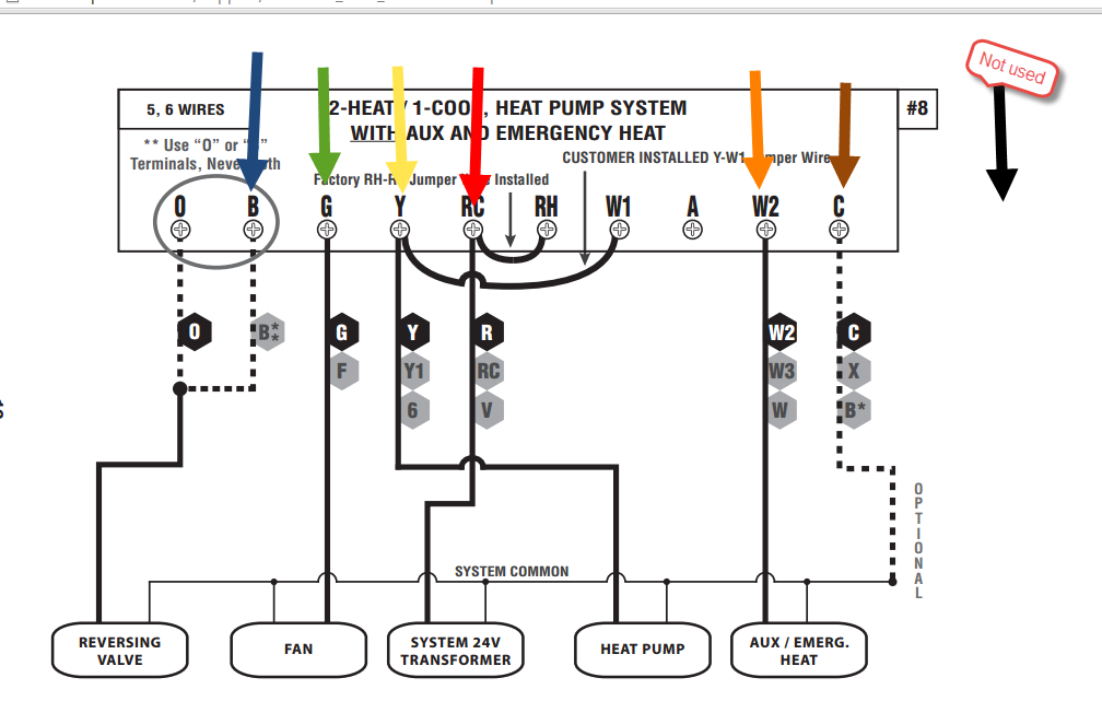
Photo Credit by: bing.com / thermostat ruud honeywell goodman ton justanswer ww2 hvac schematron chanish schemas
Goodman Heat Pump Wiring Schematic - Free Wiring Diagram

Photo Credit by: bing.com / wiring goodman pump heat diagram schematic thermostat outdoor
Dual System (heat Pump With Gas Furnace) Turning Gas Heat On When Cool

Photo Credit by: bing.com / heat furnace pump gas dual system wiring diagram turning selected cool when hvac wires fixing matter probably handle thank run
Rheem Heat Pump Low Voltage Wiring Diagram

Photo Credit by: bing.com /
0 Response to "Heat Pump Wiring Diagram Schematic"
Post a Comment